Friday, June 29, 2018

How Offshore Design Partners Save Time and Money

Despite several global challenges, the construction industry is still experiencing robust growth. Effective architectural and MEP (mechanical, electrical and plumbing) design holds the key. Cost-effective and high quality architectural and MEP design services can have a noticeable effect on the construction industry’s progress. Interestingly, outsourcing production support for drafting, Revit modelling, Revit MEP and MEP coordination presents an expedient opportunity to save time and money.


Just what services can offshore design partners offer? 

Although, offshore design support services abound, some of the most useful services that can be outsourced are MEP drafting, MEP modelling, MEP coordination, architectural drafting, architectural modelling and rendering. We look at what these services require and what they can deliver:

MEP Drafting:
Designs and marked images received as input are converted to MEP CAD drawings

MEP Modelling:
MEP CAD drawings used as input can generate MEP systems that define spaces and zones in mechanical, electrical, plumbing and fire models for all stages of the MEP design process, such as concept, tender, contract, coordination, approval, construction and as-fitted stages.

MEP Coordination:
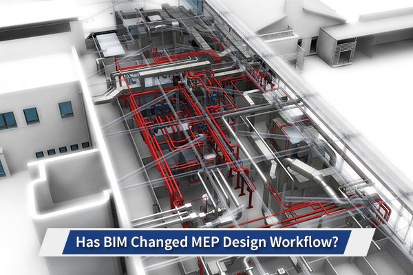
MEP models can be spatially coordinated with building services (HVAC, pipework, public health and electrical systems) with other disciplines making up the building structure, architectural elements, fabric and external envelope (steel, concrete, false ceilings, etc.) to ensure there are no clashes (validated using clash detection software tools), represent mechanical components accurately, help create views, sections and detailed drawings easily and quickly, provide easy communication, as the 3D model can be viewed and walked through for demo, review, value engineering or QC purposes by building services trades.

Architectural Drafting:
Architectural CAD drafting services can be provided for all stages of a project, including tender, planning, construction and facility management for industrial, commercial, retail and residential projects. Design partners can deliver complete construction drawing sets (incorporating space planning, interior design and construction). Sheets (plans, elevations and sections) can be created.

Architectural Modelling:
Architectural 3D modelling services increasingly use Collaboration for Revit (C4R) and BIM 360 Team, a cloud-based tool on Revit, so that teams from different locations can work on the same model. Different kinds of models that can be provided are Revit BIM 3D models, which can incorporate changes to schedules, plans, elevations, sections or the 3D model itself, resulting in coordinated updates to all corresponding areas, point cloud 3D BIM models, that take 3D laser scan data in the form of ‘point cloud’ data and use it to create accurate Revit BIM models, 3D CAD building models, created using Autodesk Revit, ArchiCAD and AutoCAD Architecture by using 2D layout plans and elevations as a starting point, SketchUp models, which have the flexibility of being used in a number of other applications, including Revit, AutoCAD and virtual software applications, 4D CAD models, which are 3D models with the added element of time-based scheduling.

Architectural Rendering:
Architectural 3D rendering is an efficient communication tool for internal design approvals and reviews during the conceptualisation and design phases. It helps construction teams view proposed layouts and is also used for effective marketing and presentation. Renderings are created from detailed 3D models (which could be in Revit or AutoCAD) using plans/elevations. The 3D model is then exported to 3ds Max where textures, materials, reflection, depth, lighting and other features are added. 

For many companies, these services can be expensive, time-consuming and require significant investment in software, hardware and training. Offshore design partners, especially in countries like India, offer these services at cost-effective rates, quicker turnaround times and of high quality. There are several reasons for this.

Benefits of Outsourcing Design Services

Architects and engineers offshore are well qualified and have the experience to provide high quality design services. Companies in this industry have been providing these services for decades and are fully cognisant of diverse global business requirements. Other reasons include: 

  1. Lower Costs - Design services are provided at affordable rates, resulting in Western companies saving designing costs, without compromising quality.
  2. Infrastructure - Overseas design support teams have access to sound technical infrastructure, generally working on cloud-based storage and high-security data back-up solutions.
  3. Quality Control - The quality checking processes ensure that the design projects delivered are accurate and error-free.
  4. Latest Technology - Software, tools and technology used are the latest available, including AutoCAD, Revit, Inventor, SolidWorks, 3ds Max, etc.
  5. Security - Confidentiality agreements and strictly monitored data security ensure intellectual safety.
  6. Skilled Personnel - Architectural and engineering teams are put through many comprehensive sessions of hands-on work, making them well capable of dealing with even the most complex requirements.
  7. Fast Delivery - Multiple teams, dedicated teams and global delivery centres follow an efficient process to complete projects on schedule.
So, offshore drafting, 3D modelling, MEP coordination with Revit MEP support and Revit MEP resources and rendering services provided by reputable offshore design partners may lead to an efficient business process that works out to be economic, fast and reliable for the long term.

Thursday, June 21, 2018

Has BIM Changed MEP Design Workflow?

BIM Influence on MEP Design Workflow

Critical to effective construction, MEP (M&E or mechanical, electrical, plumbing) design is both one of the key features of a structure and also the one design feature that most people don’t want to deal with, unless something goes terribly wrong with any particular aspect of it. This makes it all the more important to make MEP design as precise as possible. Over time, MEP design has improved and evolved in many ways, but with the arrival of BIM (Building Information Modelling) technology, MEP design has seen modifications in its workflow as well. The workflow of MEP design has been significantly influenced by BIM technology, specifically the roles of the MEP designer and the MEP contractor. 

Has BIM Changed MEP Design Workflow 

Currently, there are five different MEP design workflow scenarios that exist. They are as follows:
  1. Traditional 2D design and 3D BIM coordination
  2. 3D MEP design and 3D BIM coordination
  3. Designers 3D BIM design and coordination
  4. Contractor 3D BIM design and coordination
  5. General contractor 3D model coordination
It is the third workflow that Is becoming increasingly popular. Let’s look at why that is so.

Designers 3D BIM MEP Design and Coordination

This MEP design workflow method is a direct consequence of BIM and promotes the benefit of BIM more significantly, as it gets closer to the ‘virtual design and construction’ aims of the industry. In this workflow, the approach of the design engineer is to create a BIM model that is spatially coordinated, using the actual specified components for the project. Typically, the consultant during this phase will have more time to create the model, allowing him to absorb the changes from structural and architectural disciplines as they progress through the detailing stages. Since the model is then coordinated with the structure and architecture as well as other MEP services, the consultant can create a model according to installation standards and which is more usable by an installer or fabricator.

When the model in this workflow method is passed on to a contractor, the contractor may still wish to make final changes and adjustments in a round of value engineering. Typically, the contractor will use the same model in this workflow and make changes to the model provided by the MEP design consultant. Additionally, it is probable that the consultant engineer will not have provided invert (height) levels or dimensions from gridlines and walls for the MEP services on his drawings. In such cases the contractor will therefore have to create more detail in the drawings, but again, the contractor could use the consultant’s drawings and progress them in more detail for his/her use. This design workflow will require competent BIM coordination and MEP modelling teams and resources. XS CAD, with its large MEP coordination team and MEP engineering design team, which consists of mechanical and electrical engineering professionals, is well placed to deal with such projects for companies based in the USA, UK, Canada, Australia and New Zealand. As all are regions where BIM is now the preferred solution, XS CAD, with more than 16 years’ experience and a presence in each market is an ideal option for such companies.

Tuesday, January 30, 2018

Key to Success in Implementing VDC

The virtual building design industry is seeing an upward trend worldwide and one of the key components driving this trend is the successful implementation of VDC. Virtual design and construction (VDC) is a process that provides a single platform for all project stakeholders to collaborate and make changes in a project, while working to budgets and deadlines. One of the main features of VDC is that it uses models and data to encourage regular communication between all stakeholders right till completion. What optimises success with VDC is the contribution of qualified professionals who deliver services quickly and at lower cost.


One of the benefits clients enjoy from the VDC process is that they are provided with building information modelling (BIM) capabilities and information that help in design, project planning and construction. Collaboration between clients and contractors at earlier stages are enabled by the use of VDC. Thus, the need for rework is reduced, and project time and costs are saved.

Changes are managed, workflow is collaborated, and documents are monitored in VDC. By identifying key goals, technical concerns are addressed early on. A cloud-based working environment helps collaboration in VDC. BIM in the construction industry facilitates the creation of a single model from design specifications, RFIs and equipment data sheets, helping clients monitor the progression of the project.


Thus, VDC helps firms to:

  • Envision, modify and improve a project without wasting time or materials
  • Collaborate between contractors or subcontractors and clients
  • Establish sustainable elements into design
  • Track labour, materials and schedules for project completion
  • Provide digital delivery of plans for fabrication
Consultants and MEP professionals must work effectively for the overall success of the VDC process. Consultants manage design, but coordination and installation are usually handled by separate trades – mechanical, electrical, plumbing, etc. Smooth implementation of VDC benefits all stakeholders concerned. By using BIM 360 Glue or Revit BIM software tools during design phase coordination, the model can be sent from design to construction. Also, coordination in VDC facilitates prefabrication. BIM modelling tools in VDC streamlines MEP coordination, identifying and resolving conflicts.

The results of successful and effective VDC implementation include:

  • Complete fabrication of MEP elements
  • Reduction of rework for mechanical subcontractors 
  • Less conflicts at field installations
  • Fewer RFIs occur in MEP coordination
  • Significant savings in cost and time
Usually, coordination and installation are carried out by separate trades in the VDC process. Each may not have enough skills or resources to fully implement effective VDC, so profitable and timely delivery of projects could benefit from the right design partner. 

Advantage of Overseas VDC Experts

General contractors usually have their own teams, but they do not always have enough modelling resources or the required skillset. VDC implementation requires expertise in handling precise data with the right tools.

It is, therefore, preferable to employ a VDC expert from the relevant disciplines, who brings technical knowhow and experience in BIM virtual construction to the table. Western firms increasingly find that such experts are being located overseas, especially with experienced partners who have a large pool of qualified technical professionals and extensive experience working in the US, UK and other Western markets, leading to accurate design services, greater profits and on-time deliveries.

Tuesday, December 12, 2017

Benefits of Collaboration for Revit (C4R) in Construction

Construction projects today involve teams working simultaneously from wide-ranging geographical areas, across towns, states or even countries. These teams coordinate on the same project at the same time, using a work-sharing method that is efficient, transparent and extremely accurate. Revit Architecture services used with Collaboration for Revit (C4R) for 3D BIM coordination plays an important role in fulfilling this requirement. 

A cloud-based worksharing tool, Collaboration for Revit (or C4R) is hosted on the cloud. BIM 360 Team (formally A360 Team) is required for users wishing to upload Revit files to C4R. In the event that a stakeholder does not have Revit and C4R, they can use a web browser to access BIM 360 Team for ‘view only’ access, which provides a range of marking up and viewing formats to use. They can preview models, upload and download other project documents too. All team members can access central models stored in a file at a network location. 

As cloud computing is increasingly used for storage, sharing and hosting of models, the need to use a tool that brings a team together with minimal training time and maintenance is required. Using BIM 360 Team, C4R provides access to, and collaboration on, central Revit models on the cloud to project teams across varied disciplines, locations and companies, so that stakeholders from any location can add, delete or modify elements of the project at any point. This way, changes can be reviewed by others and necessary action can be taken. In effect, C4R allows countrywide or international teams to work simultaneously across different time zones and collaborate in real-time, a form of Revit work sharing.

C4R Uses BIM 360 Team: C4R hosts a Revit model in a centralised location called the BIM 360 Team Hub. A BIM 360 Team Hub must be created before a model can be shared via C4R. Thus, the cloud can be used to share, store and communicate. 

For Revit users, C4R need not be separately installed. It is part of Revit and provides several options in the ‘Collaborate’ tab. Revit users will however need to be assigned to a BIM 360 Team project to use C4R features. 

Easy Communication: C4R Communicator is a chat feature in Revit, with extras. Communicator connects users in the same model, in a different model but same project, or in a completely different C4R project. Chats are in real time and communication includes sending messages, files, screen shots from Revit and even the chat log. Timeline tracks comments, who is synchronising in real time, who completed and when it was completed.

Integrated Project Delivery: C4R facilitates the sharing of server requirements and centralised systems by joint design ventures from separate locations. This allows architects and engineers to communicate and share data easily and practice informed decision-making.

Cloud-based Technology: 

Since most C4R tools are cloud-based, methods and client involvement enjoy almost total flexibility, greatly reducing downtime and rework. 

  • Management – Permissions and restrictions set up in a BIM 360 Team project in Revit help manage the models.
  • BIM 360 Integration – Stakeholders, non-Revit users also, can view, comment and mark up models through a browser.
  • Communicator Tool – Communications can be on direct, real-time chat in C4R, within BIM project models.
  • Publishing Tool – Models and 2D sheets in the cloud are published with the default 3D view, allowing communication between disciplines after updating changes. 
Financially, C4R projects save an average of 30 minutes per individual team member every week. Over an entire year, this could mean that C4R can pay for itself while providing significant advantages to project teams.

Technical Issues and Autodesk Support

The platform is actively supported by Autodesk to ensure uptime. Some examples of technical issues and how they are dealt with include:

When there are bottlenecks in the code, capacity scaling under varying loads, intermittent connectivity: -Product teams across the cloud ensure that services have the right approaches and architecture to carry out their operations consistently and with high levels of reliability.

When there are degradations or outages - Services are designed so that dependencies are ‘soft’ and don't bring down core products.

When there is deviation from operational behaviour - Services are constantly logging operation results for ‘health checks’. Notifications of deviation of behaviour occur within minutes and can be rectified quickly. In addition, data trends are studied for usage patterns to improve capacity. 

Ultimately, C4R may be a better fit for many firms that require easy-to-use and easy-to-operate cloud-based solutions for collaborating on their projects. Unlike so many forerunners in the online collaboration industry, C4R actually allows collaboration and working on the same model and files rather than act as a sophisticated file exchange system.

Tuesday, August 1, 2017

Why Use Point-Cloud Scans for Architectural & MEP BIM projects?


The use of laser scanning, and in particular point cloud laser scanning has been popular now for a number of years.  Increasing renovation and refurbishment projects, especially for older buildings, means that rather than demolish a building and rebuild on the site, an existing building can be updated, allowing use of the existing facade, while changing the interior to modernise or improve the layout for the uses that are required.

The use of an accurate model to define the ‘existing condition’ of a building before any further design work is undertaken is essential for both, architectural as well as engineering teams.  Until the laser scanning surveys using 3d laser scanning technology were introduced, a physical survey of the building was the only way in which to obtain an accurate survey of a building.

The advent of CAD and BIM technology used during design stages has called for accurate 3D architectural modeling from the start and therefore 3d laser scanning is a much more accurate and useful tool for such purposes. 

While considering the benefits for both architectural and MEP projects, the benefit of using point cloud scanning is profound.

Firstly, for an architectural project, there is usually a call for the re-design of the architectural space inside a building. These may be changes, mainly to the internal space may also impact some external aspects, either way, an accurate representation of the current model is required because existing drawings may be outdated or maybe too old to use in the digital environment. Once a laser scan is completed, the creation of a 3D BIM model for the existing space makes the architectural design much easier. Typically, architects will also use existing plans and information as well as the laser point cloud scan to create the new ‘existing condition’ model, although they will predominantly rely on the laser scan data for creating a new model and associated architectural layout drawings or general arrangements (GA’s).

In most cases, the MEP systems are not taken from an existing laser point scan survey and modelled.  Rather, in most cases, the MEP systems are created from a clear base and are based on a new design altogether to suit the new purposes and uses of the refurbished building.

For building service engineers and BIM modellers, the laser scan model is therefore also extremely useful.  The remainder of this blog focuses on the existing MEP services being completely stripped and therefore not those that may have appeared in the laser point cloud model, allowing for a new set of services to be added.

The importance of 3D architectural modeling created from point cloud laser scan for building services engineers and designers can be summarised as follows;

Awareness of architectural and structural elements - For MEP modelling an accurate architectural model will provide exact information about false ceiling levels, upstand beams, columns heads, external and internal walls.  It will also provide information about riser areas and core services areas. MEP design engineers will then work around these architectural and structural elements when mapping out their services.

Builders work holes - When planning larger MEP services such as drainage sprinkler and ductwork, an MEP engineer will create builders work or penetration openings in the structure of the building. The point-cloud data for MEP engineers will show existing builders work and penetrations and therefore this information can be helpful. The building services designer may choose to use the existing holes (saving additional work) or request new holes for his/her services to pass through.

The accuracy of drawings – When a 3D BIM model is created, the BIM modeler will also create a number of coordinated drawings and single services drawings. These drawings include dimensions on them and these dimensions, especially for refurbishment projects are usually taken from existing walls and existing slab levels and floor levels. If the floor levels and all levels are based on an inaccurate model, then the MEP installation will also fail to some extent.  The point cloud model and the accurate dimensions created from the same are therefore of significant value.

As discussed, the use of laser point - cloud 3D survey models for architectural purposes and also MEP services in particular, can be critical for a refurbishment project.  Reliance on the data from the laser scan survey, assuming an accurate 3D model is created from that data, is very important to avoid construction issues and delays. Compared to legacy drawings, which may or may not have been updated, or traditional manual surveys, the accuracy of laser cloud scans and the models created from the same, will continue to remain an important aspect for modern construction design to meet cost and schedule challenges.

Tuesday, June 20, 2017

Understanding Lux Level Requirements for Commercial Lighting Design

MEP Engineering Design | MEP Design Service

Lighting design plays a key role in commercial buildings which are typically used by people to perform a task or conduct an activity. To achieve their tasks or activities in a workspace, the right amount of illuminance is necessary, over-lighting is as much as a hindrance to accomplishing tasks as under-lighting. Commercial lighting compared to industrial or residential lighting involves higher initial costs, higher maintenance, longer durability and lifespan and higher service costs. To identify the illumination level requirements or lux level requirements of a commercial building, it would be useful to understand the units of measurement of illuminance, the intensity or amount of light and the efficacy of the relationship between lux and lumen.

Illuminance or lux is the intensity of the level of light and ‘luminous flux’ or lumen is the amount of light produced. Lux is the unit of measurement usually measured in foot candles, one lumen is the measurement of the intensity of the light output and is equal to one lux across an area of one square meter. Given an area you may need to illuminate, the measurement of lux helps you identify the output or lumen required. Typically, for an office which is brightly lit around 400 lux of illumination is required and an office space which uses 100W incandescent bulbs in ceiling panels would produce 1600 lumens as the output of light. When a lighting design company designs light fixtures for a large commercial area, the number of light fixtures is usually increased to get higher lumen keeping in mind the lux level requirements.

A primary factor in ensuring efficiency in light design is achieved by balancing lux and watts or managing the amount of power used to produce light. The measurement of energy efficiency or the power required for light fixtures (luminaires) to operate is known as watts or wattage. The rate at which a light fixture converts power to light or watts to lumen is known as luminous efficacy and measured in lumens per watt (LPW). Typically, an office or commercial space with ceiling panels which would use 32W T5 or T8 fluorescent lamps would usually produce 50 lumens/watt.

Lux level requirements are calculated to determine the appropriate number of lights, the type of light fixtures and the best possible commercial lighting solution, based on the size of the office or commercial space, the type of task or activity which will be conducted and the energy efficiency standards required.

In most cases, based on the client requirements of lux levels, office spaces are over-lit and are usually more than rates mentioned in the lighting standard codes and guidelines developed by professional lighting bodies. Lighting consultants and MEP engineering design teams while keeping in mind client requirements must also consider lighting codes and guidelines which mention the minimum lux level requirements that need to be maintained. Several lighting professional bodies have published handbooks and guidelines, some of which include lighting guides published by the Chartered Institution of Building Services Engineers (CIBSE) in the UK, the IESNA Lighting Handbook by the Illuminating Engineering Society of North America and guides and lighting codes provided by the Lighting Council Australia.

To improve energy efficiency and reduce consumption, several countries have presented lighting codes and green building solutions which have made lighting manufacturers develop higher energy efficient light fittings. For offices and commercial spaces, the stipulated lighting watts/m2 is considered to be within the range of 10 to 15 watts/m2. With the increase in the use of LED light fixtures, lighting consultants are required to maintain lighting watts within the range of 5 to 8 watts/m2, while maintaining lux level requirements.

To ensure commercial lighting designs provide higher energy efficiency, lower energy consumption and better control on energy usage, lighting consultants and MEP engineering design teams must consider trending lighting solutions in the industry. From LED fixtures with advanced lighting controls, energy harvesting technologies, interactive lighting to connected lighting, there are several trends which a lighting design company could use to provide high energy-efficiency and customer-centricity in lighting design solutions for commercial spaces.

Thursday, June 8, 2017

Why MEP Contractors Change MEP Design Models

Revit BIM | MEP Consultant | MEP Design Service

In the MEP environment, a building’s MEP designs are initially developed at high level and then detailed to make them clash free and installation ready. MEP designers/consultants play a significant role in design decisions, construction planning, cost estimation and documentation. While design development is typically the role of the consultant and design detailing is done by the MEP contractor, when using MEP (M&E) BIM models and Revit BIM libraries, contractors invariably need to make changes to the MEP design model created by the consultant. 

To make a design installation ready, contractors may have to make several changes to the design-intent such as resizing of ducts, re-routing of pipework, adding wall penetrations, bolt locations and datum points for hangars and changing equipment. Once these changes are made by the contractor, the design would be installation ready and will need to be approved by the MEP consultant. The question that this article seeks to answer is why do MEP contractors need to make these and other changes to MEP design models?


  • To adjust invert elevations – During the installation of plumbing or drainage pipes, MEP contractors deal with the point of the bottom inside of the pipe, this is known as the invert elevations. To guide pipe design and match the invert elevation height, elevation information can be vertically adjusted at the centre of the pipe using Revit. However, if you are unaware that the elevation information is in centre of the pipe, it could cause confusion in adjusting invert elevations and create discrepancies while coordinating with other disciplines. This is the reason why MEP contractors need to manually adjust invert levels, create spot elevations for the inside bottom of the pipe and change the design models to install pipes which are coordinated with other disciplines. 
  • To retrofit MEP systems into a prefabricated module environment – Planning for prefabrication of MEP components into the 3D model would not be considered by designers and therefore the contractor is the party who will make adjustments to services to allow them to fit into prefabricated modules to maximise the advantages that are gained from off-site fabrication. In several MEP projects which require prefabrication of risers, ceilings and plant room areas, MEP services drawings and modules specifically for fabricators and installers is necessary to facilitate proper installation. MEP contractors make changes in the MEP design model to ensure that services fit within modules within the ceiling or riser space to allow prefabrication of MEP components off-site allowing faster installation on-site.
  • To facilitate efficient spatial coordination – When installing MEP systems, effective spatial coordination with other building services and disciplines is imperative. A consultant may leave clashes in a model as his focus will be on getting a design issue by a due date. A contractor is more concerned with actual fitting so after conducting a clash test on the 3d model, MEP contractors will invariably change design models to ensure that all services are not clashing. The installation programme of the MEP system depends on clash free layouts and MEP contractors must make sure that MEP systems are spatially coordinated with other disciplines in the 3D model before creating M&E (MEP) Coordinated Drawings.
  • To deal with constructability issues – There are several factors that influence the constructability or sequence in which MEP systems are installed. Some of the conflicts that require a change in MEP design include routing, fitting and sequencing of large equipment within a given space, conflicting piping network and installation of MEP systems within a crowded space. As MEP contractors need to tackle several conflicts and constructability issues before installing MEP systems, a change in MEP design usually occurs. 
  • To install MEP systems economically and efficiently – While the MEP design intent may seem to be perfectly coordinated, it need not necessarily be economic or efficient when it involves installation. There are several costs involved when changes need to be made after installation such as re-routing pipes to reduce bends, re-positioning ducts to allow supply and extract in the correct locations, changing equipment or adding wall penetrations, bolt locations and datum points for hangars. To make sure that MEP systems are installed economically and efficiently, MEP contractors must make changes to MEP design models.
  • Changes in materials and components – In some cases the MEP model from a consultant is accurately modelled with specified parts, materials and components. However, in some cases projects do not have specified parts and a consultant may use library elements from Revit leaving the contractor to update the model using his planned procurement schedule. This will result in changes due to sizes and access requirements for new components such as a change from copper to plastic pipe which is thicker or a change from one set of pumps to another that may be larger and may have different valve arrangements. The knock-on effect of such component changes can mean that other systems also need to be changed. 

Given the many reasons why MEP contractors need to change MEP designs and with the adoption of MEP (M&E) BIM practices, there is an overlap in the scope of MEP contractors and consultants during the planning phase. To know more about how you can reduce the duplication of efforts, additional costs, manage project schedules and reduce scope overlap, read more in this post to find out the possible routes that can be taken.

To ensure MEP design models are installation ready for MEP contractors to use on site, a viable solution would be to work with a 3D BIM coordination specialist or MEP engineering design service provider. At XS CAD, our experienced team of MEP designers in India provide BIM support and spatially coordinated building services drawings for key stakeholders in the MEP (M&E) industry, from MEP (M&E) consulting engineers and MEP (M&E) building services contractors. In our spatially coordinated MEP building services models, we use the latest 3D MEP (M&E) modelling software (Revit MEP) and clash detection technology (Autodesk Navisworks) to provide 3D M&E (MEP) coordinated drawings which adhere to engineering standards, the structural and architectural elements within a building.